Using the Global Positioning System for Coastal Monitoring
Richard C. Daniels & Peter Ruggiero
Department of Ecology
Coastal Monitoring & Analysis Program
P.O. Box 47600
Olympia, WA 98504-7600

 A word slide describing the basic methods used by the Global Positioning
System (GPS) to calculate location based on known satellite locations.
A word slide describing the basic methods used by the Global Positioning
System (GPS) to calculate location based on known satellite locations.
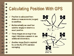 A word slide showing how distances are calculated between satellites
and the receiver on the ground.
A word slide showing how distances are calculated between satellites
and the receiver on the ground.
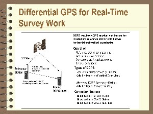 A word slide showing how the derived GPS location for a point may
be improved by the use of two or more receivers with one receiver
located at a point with known X, Y, Z coordinates.
A word slide showing how the derived GPS location for a point may
be improved by the use of two or more receivers with one receiver
located at a point with known X, Y, Z coordinates.
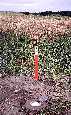 Example of a new style National Geodetic Survey vertical control
station (benchmark). This one is located in vegetated dunes near
Astoria, OR.
Example of a new style National Geodetic Survey vertical control
station (benchmark). This one is located in vegetated dunes near
Astoria, OR.
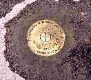 Example of an old style National Geodetic Survey horizontal control
station. This one is located near the Pacific Ocean on a World
War II observation bunker near Astoria, OR.
Example of an old style National Geodetic Survey horizontal control
station. This one is located near the Pacific Ocean on a World
War II observation bunker near Astoria, OR.
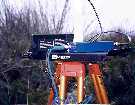
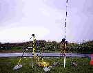 A real time kinematic (RTK) GPS system with a 2-meter fixed height
tripod with a L1/L2 GPS antenna with groundplain setup over a vertical
control station. The large yellow box at the base of the 2-m tripod
contains a Trimble 4000SI base receiver. The blue and white pole
is the radio antenna that sends real time corrections to other
roving GPS receivers. These corrections allow the roving receivers
to correct their point location to within +/- 1 cm.
A real time kinematic (RTK) GPS system with a 2-meter fixed height
tripod with a L1/L2 GPS antenna with groundplain setup over a vertical
control station. The large yellow box at the base of the 2-m tripod
contains a Trimble 4000SI base receiver. The blue and white pole
is the radio antenna that sends real time corrections to other
roving GPS receivers. These corrections allow the roving receivers
to correct their point location to within +/- 1 cm.
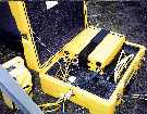 A Trimble 4000SI receiver showing cable connections for the L1/L2
GPS antenna, battery, and external radio (blue cable).
A Trimble 4000SI receiver showing cable connections for the L1/L2
GPS antenna, battery, and external radio (blue cable).
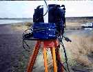 A Pacific Crest 35-watt radio connected to the base GPS receiver.
This radio is used to send real-time radio corrections to the roving receivers.
A Pacific Crest 35-watt radio connected to the base GPS receiver.
This radio is used to send real-time radio corrections to the roving receivers.
 Radio repeater used to extend the range over which the roving
receivers may travel by retransmitting the GPS corrections received
from the base station 35-watt radio.
Radio repeater used to extend the range over which the roving
receivers may travel by retransmitting the GPS corrections received
from the base station 35-watt radio.
 Close up of a Pacific Crest Radio Repeater.
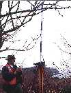
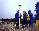 A roving receiver taking a static point (control point). Note the
L1/L2 GPS antenna on top of a 2-meter range pole and the black radio
antenna attached to the backpack. This antenna allows the roving
receiver to receive the GPS differential corrections broadcast by
the base station radio.
A roving receiver taking a static point (control point). Note the
L1/L2 GPS antenna on top of a 2-meter range pole and the black radio
antenna attached to the backpack. This antenna allows the roving
receiver to receive the GPS differential corrections broadcast by
the base station radio.
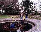 A roving receiver taking a ground control point at a feature that is
visible on 1:12,000 air photography. This point (a World War II
gun emplacement) will be used in the orthorectification process for
the air photography.
A roving receiver taking a ground control point at a feature that is
visible on 1:12,000 air photography. This point (a World War II
gun emplacement) will be used in the orthorectification process for
the air photography.
 A roving receiver taking continues data as the operator walks a transect.
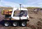
 A roving receiver mounted on a six-wheeled vehicle taking continues data.
The vehicle is being used to obtain GPS data to derive a topographic map of the beach.
A roving receiver mounted on a six-wheeled vehicle taking continues data.
The vehicle is being used to obtain GPS data to derive a topographic map of the beach.
 A roving receiver mounted on a six-wheeled vehicle taking continues data.
In this operation the GPS data is being stored into a laptop computer mounted
inside the vehicle. This allows the operator to visually monitor the vehicles current
and past location in real-time on the computers LCD screen.
A roving receiver mounted on a six-wheeled vehicle taking continues data.
In this operation the GPS data is being stored into a laptop computer mounted
inside the vehicle. This allows the operator to visually monitor the vehicles current
and past location in real-time on the computers LCD screen.
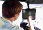 Vehicle operator navigating based on real-time position information displayed
on a laptop computer mounted within the vehicle.
Vehicle operator navigating based on real-time position information displayed
on a laptop computer mounted within the vehicle.
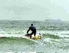
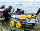 Combined GPS and ecosounder system developed by Oregon State University.
Note the L1/L2 GPS antenna mounted next the radio antenna. The
ecosounder is mounted in the hull of the personal watercraft. The GPS
data and depth data are combined to obtain detailed bathymetry data
in the nearshore region, an area not reachable by conventional surveying
methods.
Combined GPS and ecosounder system developed by Oregon State University.
Note the L1/L2 GPS antenna mounted next the radio antenna. The
ecosounder is mounted in the hull of the personal watercraft. The GPS
data and depth data are combined to obtain detailed bathymetry data
in the nearshore region, an area not reachable by conventional surveying
methods.
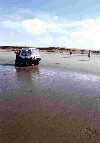
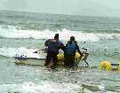 Launching the combined GPS and ecosounder system.
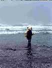
 Operation of the combined GPS and ecosounder system on the southwest
Washington coast.
Operation of the combined GPS and ecosounder system on the southwest
Washington coast.
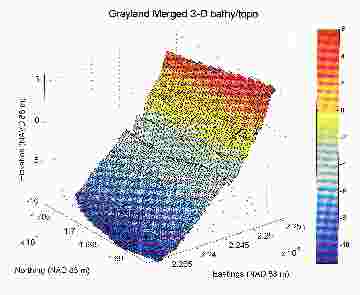 Three-dimensional topographic surface derived from combined bathymetry and GPS data in
Grayland, WA. Longshore direction is from right to left. Note the beach cusps that have
been mapped near mean low water (yellow area). Colors indicate elevations in meters above NAVD88.
Three-dimensional topographic surface derived from combined bathymetry and GPS data in
Grayland, WA. Longshore direction is from right to left. Note the beach cusps that have
been mapped near mean low water (yellow area). Colors indicate elevations in meters above NAVD88.
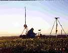 The sun setting on the Pacific behind the full suite of RTK GPS equipment.
Note that the GPS base station, 35-watt radio, and the GPS rover backpack are
visible in this photo.
The sun setting on the Pacific behind the full suite of RTK GPS equipment.
Note that the GPS base station, 35-watt radio, and the GPS rover backpack are
visible in this photo.
References
Kaminsky, G.M., P. Ruggiero, and G. Gelfenbaum. 1998. Monitoring coastal change in Southwest Washington and Northwest Oregon
during the 1997/98 El Niño. Shore and Beach 66:42-51.
Kennedy, M. 1996. The Global Positioning System and GIS, An Introduction. Ann Arbor Press, Chelsea, MI.
Ruggiero, P., J. Côté, G. Kaminsky, and G. Gelfenbaum. 1999. Scales of variability along the Columbia River littoral cell.
Coastal Sediments'99, ASCE, Long Island, NY.
Return to the Table of Contents